3. Add a display
Used includes in this chapter:
use defmt::{info, unwrap};
use embassy_executor::Spawner;
use embassy_nrf::{
    bind_interrupts,
    gpio::{Level, Output, OutputDrive},
    peripherals, spim,
};
use embedded_graphics::{
    image::{Image, ImageRaw, ImageRawLE},
    pixelcolor::Rgb565,
    prelude::*,
    primitives::{PrimitiveStyle, StyledDrawable},
};
use {defmt_rtt as _, panic_probe as _};
Next up we are going to add a display and show an image on it. In this chapter, we are going to implement the display in a synchronous manner, and later on adapt it, so we end up with an async implementation.
Connecting the display
How does a breadboard work?
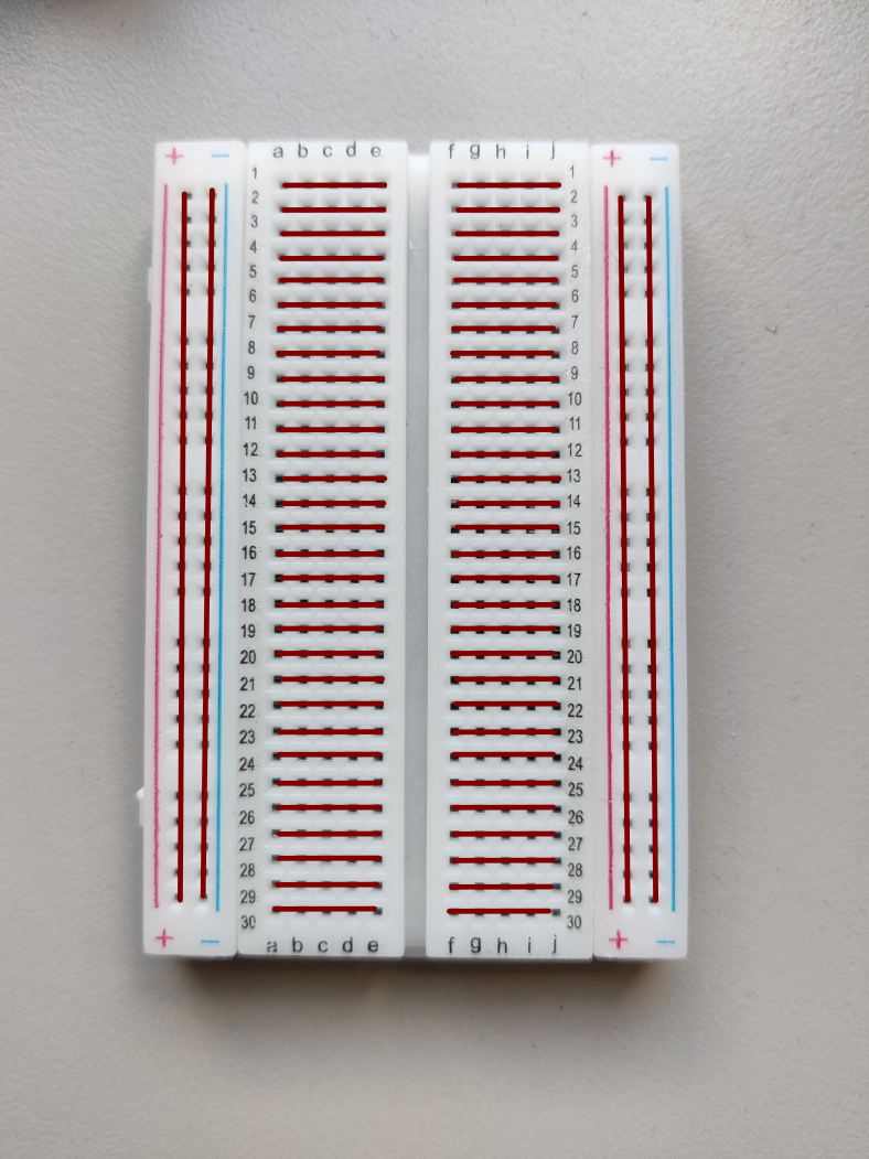
Breadboards are tools that help with quick prototyping of electrical designs. They aid by having a simple way of connecting components without soldering. The holes are connected like in the following image. So, if you want to connect two wires/components, you need to put their metal ends in one of the connected holes. As long as the holes are connected, the components will be too.
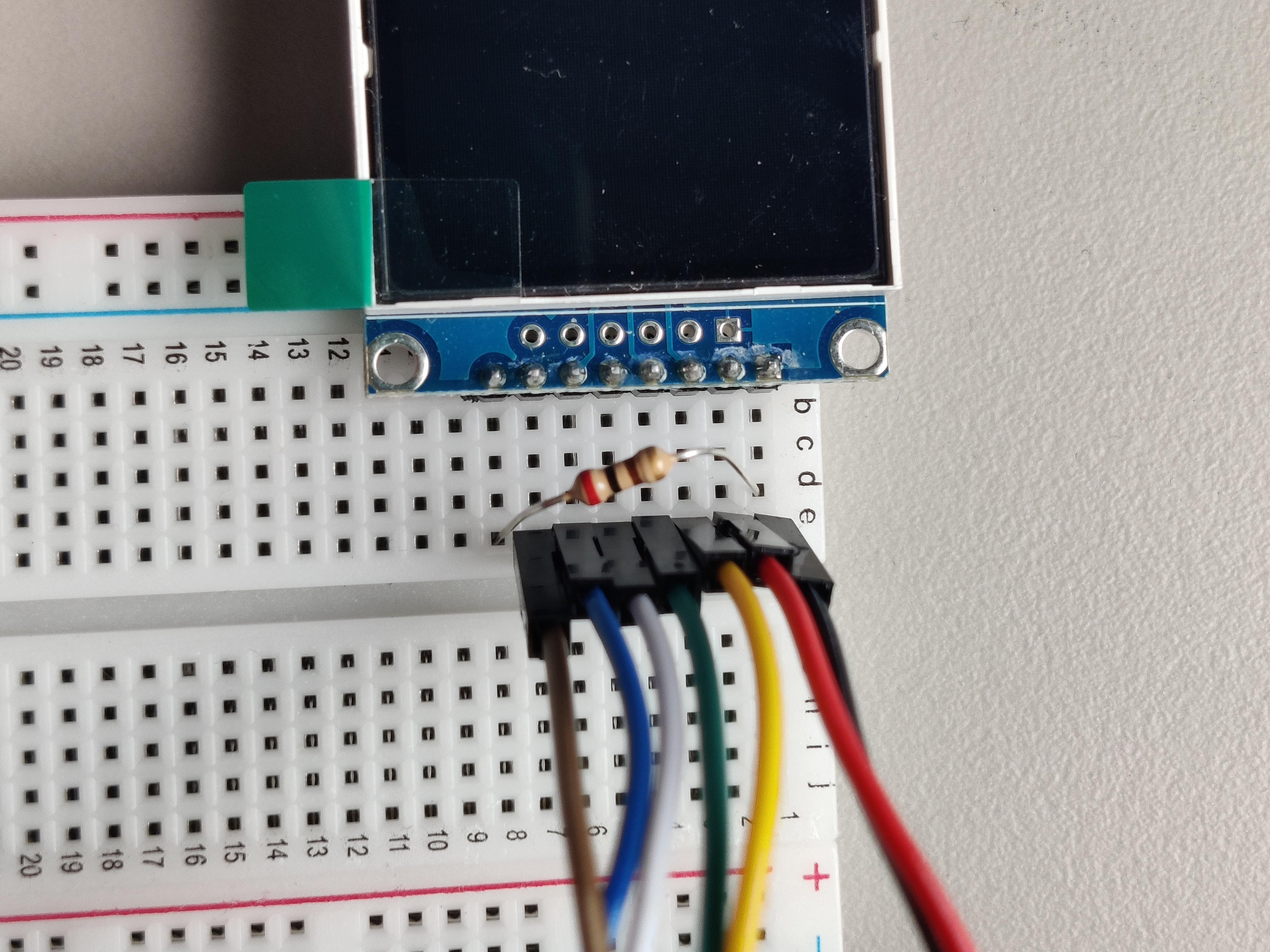
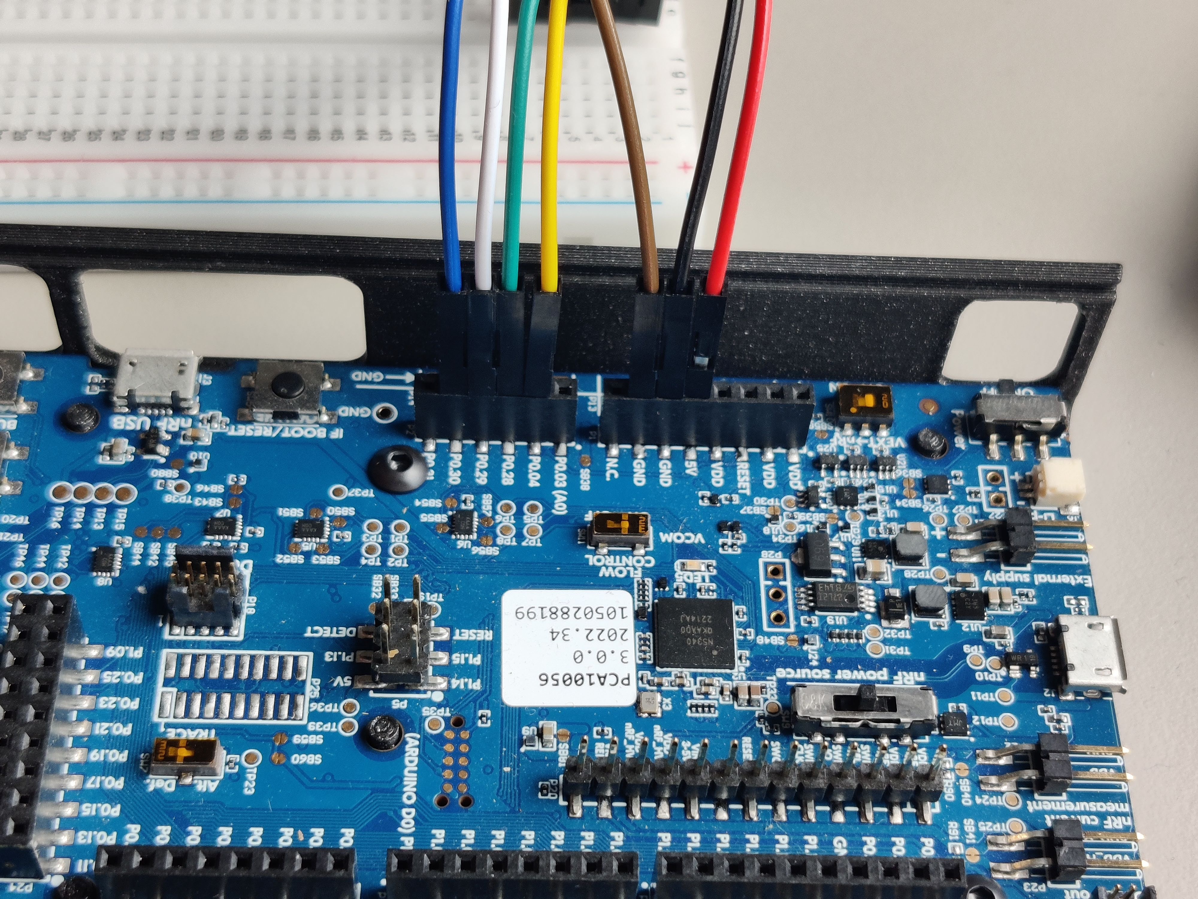
Before we can do anything with the display, we must connect it to the development kit. Make sure you disconnect everything from your computer to prevent short circuits before connecting anything. You should now connect the following pins as described below.
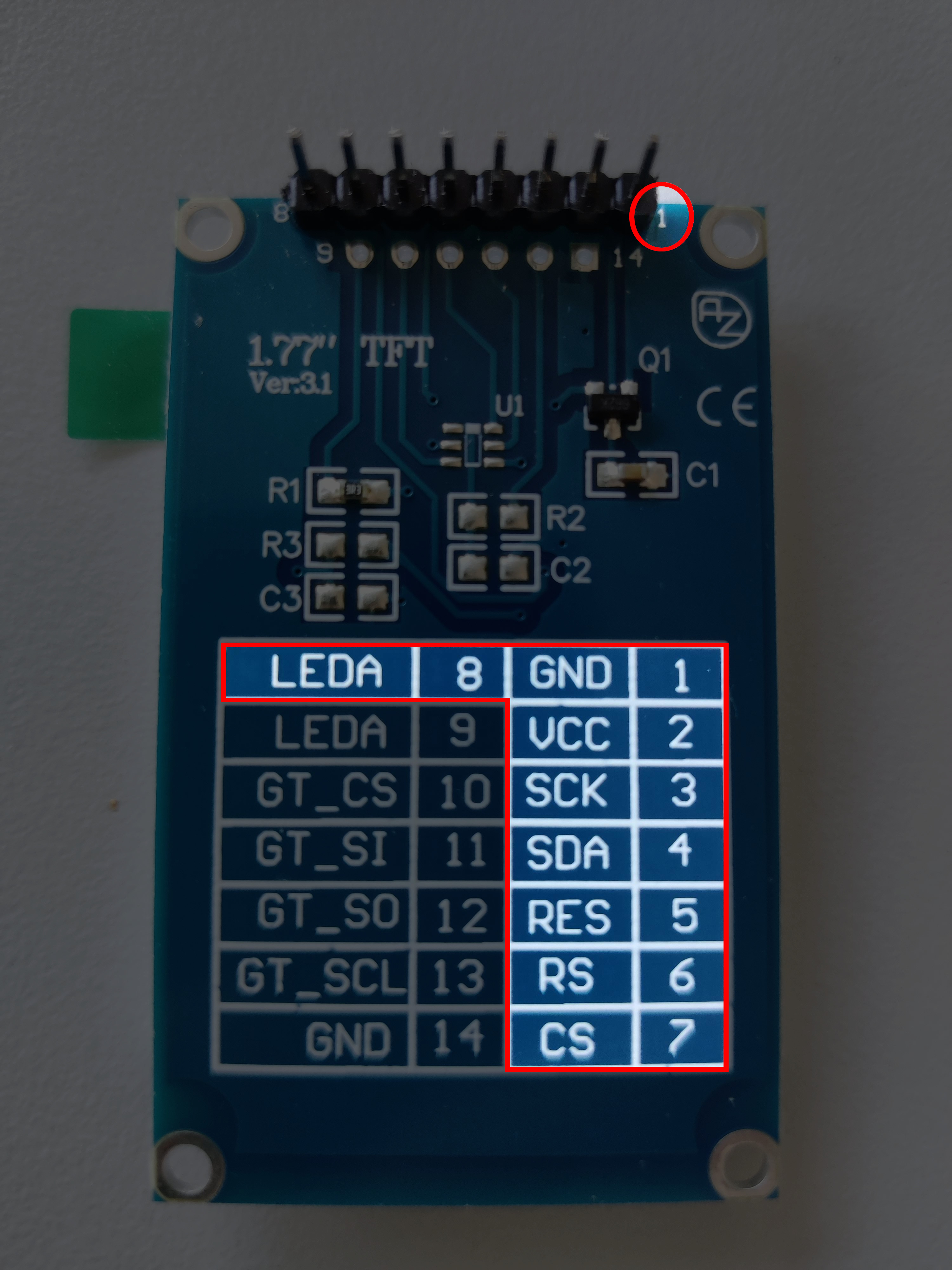
For the pins on the display, look at the back of the display where you will find the needed markings. When you are done, ask one of the course instructors to look at your wiring to verify its correctness. Once your circuit is correct, you may run the code at any time you may want to test.
| Display | nRF |
|---|---|
| Pin 1 (GND) | GND (any GND is ok) |
| Pin 2 (VCC) | VDD |
| Pin 3 (SCK) | P0.04 |
| Pin 4 (SDA) | P0.28 |
| Pin 5 (RES) | P0.29 |
| Pin 6 (RS) | P0.30 |
| Pin 7 (CS) | GND |
| Pin 8 (LEDA) | 220 Ohm resistor to VDD |
Programming the display to show an image
As some may already have noticed, this display is connected through SPI with only master-to-slave (MOSI) communication. This means we need to get a hold of the ownership of one of the SPI interfaces in the chip. The nRF chip distinguishes between master and slave connections. As such, we must use one of the master connections.
As Embassy is an async executor, it needs a way to know whether there is data to be written or read. This is done through interrupts.
For our purpose, put the following above main:
bind_interrupts!(struct Irqs {
    SPIM3 => spim::InterruptHandler<peripherals::SPI3>;
});
This will bind interrupts of the master interface of SPI3 in a way accessible for our next step, initializing SPIM3.
let mut config = spim::Config::default();
config.frequency = spim::Frequency::M32; // we will communicate at 32Mbps
let spi = spim::Spim::new_txonly(p.SPI3, Irqs, p.P0_04, p.P0_28, config); // setup SPIM3
Once this is done, our display still needs access to RES (reset) and RS ("register select", or sometimes called D/C for "data command").
These need to be put in output mode.
let res = Output::new(p.P0_29, Level::Low, OutputDrive::Standard);
let rs = Output::new(p.P0_30, Level::Low, OutputDrive::Standard);
Now we have all the necessary peripherals, we can configure the display. The needed steps are:
- Construct an instance of the display
- Send the initialization commands to the display
- Set an orientation for the display
- Draw something
We already have the peripherals ready, so the first 3 steps are easy:
let mut delay = embassy_time::Delay; // blocking delay, use with caution
// spi, rs, res, is_rgb, is_inverted, width, height
let mut display = st7735_lcd::ST7735::new(spi, rs, res, true, false, 160, 128);
display.init(&mut delay).unwrap(); // send display init commands
display.set_orientation(&st7735_lcd::Orientation::Landscape).unwrap(); // set the correct orientation
Now we have a working display, but not yet something shown on it.
Just like embedded_hal, there exists an embedded_graphics API providing a similar purpose in abstracting over multiple kinds of displays.
The driver we are using for our display supports this API, so we can use the higher level drawing commands, without needing to directly communicate with the display.
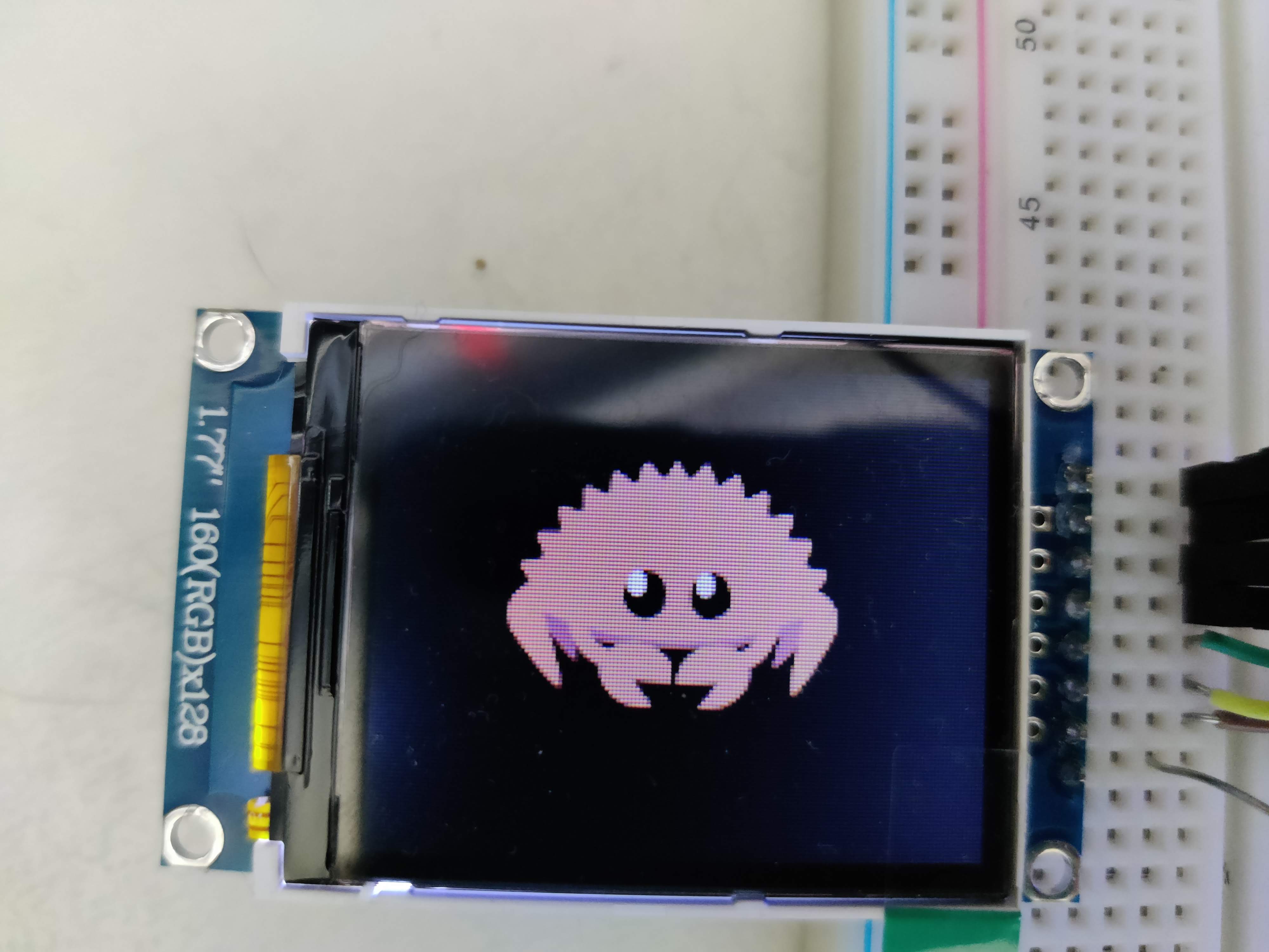
We are going to draw two things: first clearing the display by drawing a rectangle filling the entire screen, and second, an image with Ferris (the unofficial Rust mascot).
// define the rectangle and the way it should be drawn
let rectangle = display.bounding_box();
let style_black = PrimitiveStyle::with_fill(Rgb565::BLACK);

// define the image (uses one of the assets) and translates it to a desired position
let image_raw: ImageRawLE<Rgb565> = ImageRaw::new(include_bytes!("../assets/ferris.raw"), 86);
let image = Image::new(&image_raw, Point::new(34, 25));

// actually start drawing, by sending the commands to the display
unwrap!(rectangle.draw_styled(&style_black, &mut display));
unwrap!(image.draw(&mut display));
Here follows the completed example combined with the previous chapter:
#![no_std]
#![no_main]

// Ignore these following 2 lines, we are going to use these in a later chapter
// and are not important right now
mod frame_buffer;
mod game;

use defmt::{info, unwrap};
use embassy_executor::Spawner;
use embassy_nrf::{
    bind_interrupts,
    gpio::{Level, Output, OutputDrive},
    peripherals, spim,
};
use embedded_graphics::{
    image::{Image, ImageRaw, ImageRawLE},
    pixelcolor::Rgb565,
    prelude::*,
    primitives::{PrimitiveStyle, StyledDrawable},
};
use {defmt_rtt as _, panic_probe as _};

// Embassy needs something to wake itself on read/write interrupts.
// This is like a certification of ownership that we alone have access to these interrupts
bind_interrupts!(struct Irqs {
    SPIM3 => spim::InterruptHandler<peripherals::SPI3>;
});

#[embassy_executor::main]
async fn main(_spawner: Spawner) {
    let p = embassy_nrf::init(Default::default());
    let mut led = Output::new(p.P0_13, Level::Low, OutputDrive::Standard);

    // Configure SPI Master 3
    let mut config = spim::Config::default();
    config.frequency = spim::Frequency::M32; // communicate with screen at 32Mbps
    let spi = spim::Spim::new_txonly(p.SPI3, Irqs, p.P0_04, p.P0_28, config);
    let res = Output::new(p.P0_29, Level::Low, OutputDrive::Standard); // reset pin
    let rs = Output::new(p.P0_30, Level::Low, OutputDrive::Standard); // pin that helps distinguis between data and commands

    let mut delay = embassy_time::Delay;
    let mut display = st7735_lcd::ST7735::new(spi, rs, res, true, false, 160, 128); // create screen instance
    display.init(&mut delay).unwrap(); // actually send out first commands to display
    display
        .set_orientation(&st7735_lcd::Orientation::Landscape)
        .unwrap(); // set the orientation for our display

    let rectangle = display.bounding_box(); // get max bounds of display
    let style_black = PrimitiveStyle::with_fill(Rgb565::BLACK);

    // import Ferris image (note 86 as in example code for display driver 85 is written -> WRONG)
    let image_raw: ImageRawLE<Rgb565> =
        ImageRaw::new(include_bytes!("../../assets/ferris.raw"), 86);
    let image = Image::new(&image_raw, Point::new(34, 25));

    // make the actual draw calls -> SPI magic
    unwrap!(rectangle.draw_styled(&style_black, &mut display));
    unwrap!(image.draw(&mut display));

    let interval = embassy_time::Duration::from_millis(1000);
    loop {
        led.set_high();
        info!("Hello world");
        embassy_time::Timer::after(interval).await;
        led.set_low();
        embassy_time::Timer::after(interval).await;
    }
}